Computational Fluid Dynamics and Heat Transfer
Computational Fluid Dynamics (CFD) is a set of numerical methods used to analyze the flow of liquids and gases, as well as coupled heat transfer processes in complex geometric and functional systems. Our CFD services focus on solving the client’s engineering problem: from identifying key performance indicators (pressure, losses, forces, heat transfer coefficients, etc.) to delivering an implementation-ready solution along with design guidelines leading to the optimization of desired parameters.
Scope of Services and Applications
We provide CFD flow analyses and simulations tailored to specific design objectives: improving flow characteristics, reducing pressure losses, optimizing heat transfer, and analyzing the behavior of rotating machinery. Typical applications include:
- steady-state and transient flow simulations,
- laminar and turbulent flows, including transition modeling,
- flows in turbomachinery (rotor-stator) using RANS/URANS as well as DES and LES approaches,
- jet flow analyses and interactions between jets and solid bodies, as well as the surrounding environment (e.g., still air),
- coupled thermo-fluid simulations (CFD + heat transfer), including conduction in solids and convection between fluid–solid–fluid interfaces,
- aerodynamic analyses of various aircraft and vehicles,
- full HVAC system analyses for different comfort environments, e.g., in vehicles or buildings.
Computational Methods and CFD Model Preparation
The selection of computational strategy and simulation setup always depends on the physical phenomena and the objective of the analysis. Depending on the required accuracy and available computational budget, we use RANS models (Spalart–Allmaras, k-ε, k-ω SST) for efficient engineering analyses, and URANS or LES/DES approaches when unsteady effects are critical—such as flow separation, jet detachment, vortex interactions, or aeroacoustic phenomena.
In parallel, we perform careful geometry and mesh preparation. This includes defining the fluid domain, removing irrelevant geometric details, closing topological gaps, and applying local geometric corrections to improve computational efficiency. We generate all types of meshes, including hexahedral, polyhedral, and prism-layer elements, according to solver requirements and flow characteristics, while controlling quality metrics (skewness, aspect ratio, etc.) and ensuring appropriate y+ values in the near-wall region.
Solver configuration includes defining boundary and initial conditions, as well as numerical parameters ensuring stability and repeatability. We perform mesh sensitivity studies and turbulence model assessments, monitor residual convergence and mass, momentum, and energy balances, and—where possible—validate results against experimental or literature data. This approach ensures that the CFD model is engineering-validated rather than purely visual.
CFD Results and Optimization Support
Simulation results are presented in the form of technical project documentation. This includes velocity and pressure fields, temperature contours, heat transfer coefficient maps, total pressure loss analyses, as well as forces and moments acting on structural components. For turbomachinery, we provide complete performance characteristics (e.g., pressure ratio, pressure drop, efficiency curves), and for unsteady analyses—time histories of the considered parameters.
However, the key element of the report is not just the contour plots, but their interpretation. We identify regions responsible for energy losses, analyze separation and recirculation mechanisms, evaluate heat transfer efficiency, and determine which geometric modifications will yield the greatest improvement with minimal design intervention.
As a result, CFD simulations become a design tool supporting device optimization, reducing prototyping costs, and shortening the development cycle.
Integration with Other Services
Our CFD simulations are part of a broader CAE workflow: CFD models can be coupled with structural analyses (FEM) or with the acoustic module (CAA) to assess the impact of flow on vibrations and noise emission. We also provide CAD modeling services, enabling faster geometry transfer and avoiding duplication of work.
What Is Required for Quotation
For quotation purposes, we require: a description of the function and operating conditions of the device or module, expected parameters/indicators, and any other relevant project information, such as material data, whether steady or unsteady analyses are required, etc.
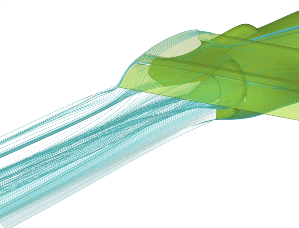
Example Application
Flow analysis through a turbofan engine exhaust nozzle—an example simulation for both uninstalled and installed engine configurations. In this class of problems, it is crucial to accurately reproduce the nozzle geometry, select an appropriate turbulence model, properly generate the computational mesh with the possibility of dynamic mesh adaptation in regions of high flow gradients, and perform a detailed evaluation of velocity and turbulence fields.
CFD simulations at UniFlow Dynamics combine numerical rigor with practical engineering interpretation. Our goal is to deliver analyses that directly improve device performance and reduce the time required to implement design changes. If you would like to receive a quotation or discuss the scope of work, please use the contact form.
